<< Previous page INDEX Next page >>
5.2 Depth of Discharge
The typical end-of-discharge voltage for nickel-based batteries is 1V/cell. At that voltage level, about 99 percent of the energy is spent and the voltage starts to drop rapidly if the discharge continues. Discharging beyond the cut-off voltage must be avoided, especially under heavy load.
Since the cells in a battery pack cannot be perfectly matched, a negative voltage potential (cell reversal) across a weaker cell occurs if the discharge is allowed to continue beyond the cut-off point. The larger the number of cells connected in series, the greater the likelihood of this occurring.
A NiCd battery can tolerate a limited amount of cell reversal, which is typically about 0.2V. During that time, the polarity of the positive electrode is reversed. Such a condition can only be sustained for a brief moment because hydrogen evolution occurs on the positive electrode. This leads to pressure build-up and cell venting.
If the cell is pushed further into voltage reversal, the polarity of both electrodes is being reversed, resulting in an electrical short. Such a fault cannot be corrected and the pack will need to be replaced.
On battery analyzers that apply a secondary discharge (recondition), the current is controlled to assure that the maximum allowable current, while in sub-discharge range, does not exceed a safe limit. Should a cell reversal develop, the current would be low enough as not to cause damage. A cell breakdown through recondition is possible on a weak or aged pack.
If the battery is discharged at a rate higher than 1C, the more common end-of-discharge point of a nickel-based battery is 0.9V/cell. This is done to compensate for the voltage drop induced by the internal resistance of the cell, the wiring, protection devices and contacts of the pack. A lower cut-off point also delivers better battery performance at cold temperatures.
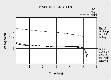
The recommended end-of-discharge voltage for the SLA is 1.75V/cell. Unlike the preferred flat discharge curve of the NiCd, the SLA has a gradual voltage drop with a rapid drop towards the end of discharge (see Figure 5-1). Although this steady decrease in voltage is a disadvantage, it has a benefit because the voltage level can be utilized to display the state-of-charge (SoC) of a battery. However, the voltage readings fluctuate with load and the SoC readings are inaccurate.
Figure 5-1: Discharge characteristics of NiCd, NiMH and SLA batteries.
While voltage readings to measure the SoC are not practical on nickel-based batteries, the SLA enables some level of indication as to the SoC.°C (77°F) with respect to the depth of discharge is:
- 150 – 200 cycles with 100 percent depth of discharge (full discharge)
- 400 – 500 cycles with 50 percent depth of discharge (partial discharge)
- 1000 and more cycles with 30 percent depth of discharge (shallow discharge)
