<< Previous page INDEX Next page >>
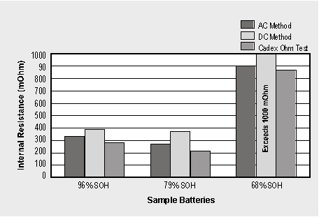
Figure 9-8 compares the three methods of measuring the internal resistance of a battery and observe the accuracy. In a good battery, the discrepancies between methods are minimal. The test results deviate to a larger degree on packs with poor SoH.
Impedance measurement alone does not provide a definite conclusion as to the battery performance. The mW readings may vary widely and are dependent on battery chemistry, cell size (mAh rating), type of cell, number of cells connected in series, wiring and contact type.
Figure 9-8: Comparison of the AC, DC and Cadex Ohmtest™ methods.
State-of-health readings were obtained using the Cadex 7000 Series battery analyzer by applying a full charge/discharge/charge cycle. The DC method on the 68% SoH battery exceeded 1000mW.When using the impedance method, a battery with a known performance should be measured and its readings used as a reference. For best results, a reference reading should be on hand for each battery type. Figure 9-9kl; provides a guideline for digital mobile phone batteries based on impedance readings.
The milliohm readings are related to the battery voltage. Higher voltage batteries allow higher internal resistance because less current is required to deliver the same power. The ratio between voltage and milliohm is not totally linear. There are certain housekeeping components that are always present whether the battery has one or several cells. These are wiring, contacts and protection circuits.
Temperature also affects the internal resistance of a battery. The internal resistance of a naked Li-ion cell, for example, measures 50mW at 25°C (77°F). If the temperature increases, the internal resistance decreases. At 40°C (104°F), the internal resistance drops to about 43mW and at 60°C (140°F) to 40mW. While the battery performs better when exposed to heat, prolonged exposure to elevated temperatures is harmful. Most batteries deliver a momentary performance boost when heated.
Milli-Ohm Battery Voltage Ranking
75-150mOhm 3.6V Excellent 150-250mOhm 3.6V Good 250-350mOhm 3.6V Marginal 350-500mOhm 3.6V Poor Above 500mOhm 3.6V Fail
Figure 9-9: Battery state-of-health based on internal resistance.
The milliohm readings relate to the battery voltage; higher voltage allows higher milliohm readings.Cold temperatures have a drastic effect on all batteries. At 0°C (32°F), the internal resistance of the same Li-ion cell drops to 70mW. The resistance increases to 80mW at -10°C (50°F) and 100mW at -20°C (-4°F).
The impedance readings work best with Li-ion batteries because the performance degradation follows a linear pattern with cell oxidation. The performance of NiMH batteries can also be measured with the impedance method but the readings are less dependable. There are instances when a poorly performing NiMH battery can also exhibit a low mW reading.
Testing a NiCd on resistance alone is unpredictable. A low resistance reading does not automatically constitute a good battery. Elevated impedance readings are often caused by memory, a phenomenon that is reversible. Internal resistance values have been reduced by a factor of two and three after servicing the affected batteries with the recondition cycle of a Cadex 7000 Series battery analyzer. Of cause, high internal resistance can have sources other than memory alone.
9.3 What’s the difference between internal resistance and impedance?
The terms ‘internal resistance’ and ‘impedance’ are often intermixed when addressing the electrical conductivity of a battery. The differences are as follows: The internal resistance views the conductor from a purely resistive value, or ohmic resistance. A comparison can be made with a heating element that produces warmth by the friction of electric current passing through.
Most electrical loads are not purely resistive, rather, they have an element of reactance. If an alternating current (AC) is sent through a coil, for example, an inductance (magnetic field) is created, which opposes current flow. This AC impedance is always higher than the ohmic resistance of the copper wire. The higher the frequency, the higher the inductive resistance becomes. In comparison, sending a direct current (DC) through a coil constitutes an electrical short because there is only a very small ohmic resistance.
Similarly, a capacitor does not allow the flow of DC, but passes AC. In fact, a capacitor is an insulator for DC. The resistance that is present when sending an AC current flowing through a capacitor is called capacitance. The higher the frequency, the lower the capacitive resistance.
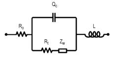
A battery as a power source combines ohmic, inductive and capacitive resistance. Figure 9-10 represents these resistive values on a schematic diagram. Each battery type exhibits slightly different resistive values.
Figure 9-10: Ohmic, inductive and capacitive resistance in batteries.
- Ro = ohmic resistance
- Qc = constant phase loop (type of capacitance)
- L = inductor
- Zw = Warburg impedance (particle movement within the electrolyte)
- Rt = transfer resistance

