This guide was written by Nathan Towne (2009-09)

Introduction
There are quite a few calculators for microstrip and stripline, and commercial products that do the same. But I was looking for a method of constructing a balun of controlled and fairly low impedances, which requires broadside-coupled stripline, where the widths of the traces mostly control the even (common-mode) impedance, and the spacing the odd (differential) impedance. I had in mind using copper tape for the traces and ground planes, polystyrene sheets for dielectric between the traces and the ground plane, and polyethylene or polystyrene sheets setting the spacing between the traces. The problem I encountered is the apparent dearth of information on the impedances of broadside-coupled stripline.
I ended up calculating those impedances using the Superfish/Poisson finite-element codes available from the Accelerator Code group at Los Alamos National Laboratory. The codes are used to calculate the capacitances of the even and odd modes by applying the appropriate boundary condition of each in a Laplace boundary-value calculation. The formula
where where μ and ε are the permeability and permittivity of the medium, respectively, and C includes the dielectric constant, is then applied to each mode's capacitance in turn.
This note gives the results of those calculations.
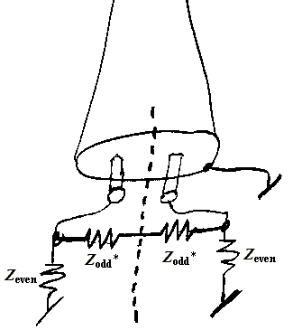
First a note about the meaning of the impedances, since there can be a factor of two between definitions. The figure to the right showing the simultaneous matched termination of the even and odd modes of a twin-lead transmission line shows how the even- and odd-mode impedances Zeven and Zodd are to be interpreted, where Zodd* in parallel with Zeven is Zodd:

With these definitions of the impedances, Zeven is always greater than Zodd, and, as the distance between the wires or traces becomes large, Zodd* becomes an open circuit, and the two impedances both approach the uncoupled impedance of each.
The following sections give the impedances of broadside-coupled twin stripline, edge-coupled twin stripline, and the impedance of single stripline. Impedances at only one value of relative trace thickness are given.
Broadside-coupled twin stripline
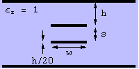
The geometry is as shown in the figure. The trace thicknesses are fixed at h/20 and the dielectric constant is one. Remember that impedances scale as the dielectric constant-1/2.
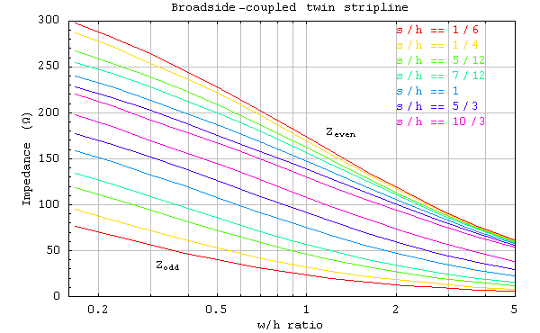
The following figure gives Zeven and Zodd as a function of w/h for values of the s/h marked on the graph.
Single-trace stripline
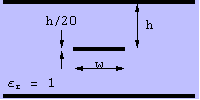
Although the impedances of ordinary stripline are readily available on the web, I include my numbers as well. The first figure gives the geometry defining the parameters. The next figure is of the impedances. The red trace shows my results, and the blue trace is the formula
Z=60 ln(1.9(2+t/h)/(0.8w/h+t/h))
that is seen on the internet here and there. The formula is quoted for values of w/h<2.
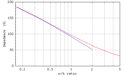
For comparison, my result at w/h=1 and t/h=0.05 is 96.1 ohms. The formula's is 91.3.
Edge-coupled twin stripline
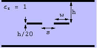
Formulas for edge-coupled twin-lead stripline are also available, although I haven't seen one that computes both impedances. The figure to the right defines the parameters of the problem and the following figure shows the impedances.
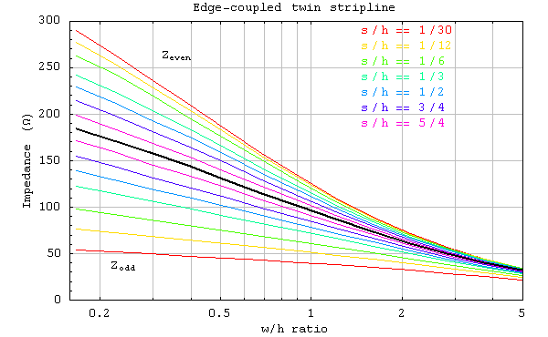
The black line is the uncoupled-stripline impedance of the the previous section. Above that line are traces for the even mode, and below are traces for the odd mode. Note that, as s/h increases, the traces converge on the uncoupled impedance much faster than for broadside-coupled lines, which reflects the much weaker coupling between the traces compared to broadside-coupled lines.
