NOTE: THIS DOCUMENT IS OBSOLETE, PLEASE CHECK THE NEW VERSION: "Introduction to Digital Filters with Audio Applications", by Julius O. Smith III, Copyright © 2017-11-26 by Julius O. Smith III - Center for Computer Research in Music and Acoustics (CCRMA), Stanford University
<< Previous page TOC INDEX Next page >>
Frequency Response
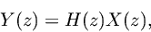
Beginning with Eq. (2.2.1), we have
whereis the
-transform of the filter input,
is the
is the filter transfer function.
Definition. The frequency response of a linear time-invariant digital filter is defined to be the transfer function,
.
The frequency response is a complex-valued function of a real variable. The response at frequency
Hz, for example, is
, where
is the sampling period in seconds.
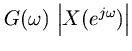
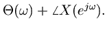
Since every complex number can be represented as a magnitude and angle, the frequency response may be decomposed into two real-valued functions, the amplitude response and the phase response. Formally, we may define them as follows:
so that
Thusis the magnitude (or complex modulus) of
is the phase (or complex angle) of
Definition. The real valued function
Definition. The function
is called the power response and it specifies the power gain at each frequency.
Definition. The real function
If the filter input and output signals are
and
respectively, then
(50) (51)